The coating chamber for the TAO telescope has been installed in the operation building at the summit
The coating system plays the role of aluminum coating to the primary, secondary, and third mirror, which are made of glass (OHARA E6) as reflectors, and reviving mirrors whose reflectivity has reduced due to dirt and deterioration caused by long-term observation operations. The features of the TAO coating system are (1) the primary mirror cell is sandwiched between the upper chamber and the lower chamber (i.e. the primary mirror cell itself works as a part of the coating chamber) during coating operation, (2) the lower chamber is integrated with the movable lifting cart to transport the primary mirror cell between the coating area and the telescope enclosure, (3) above all, the chamber at the highest observatory in the world can be called the coating chamber which is installed at the highest altitude. Therefore, there were many difficulties and challenges to transport, install, and evaluation test it. However in December 2024, we finally overcame these difficulties, installed it in the operation building at the summit, and confirmed it works without problems.
1. Transportation to the summit
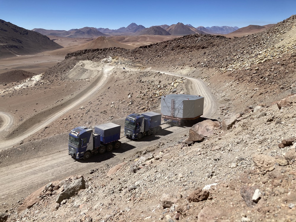
TAO is located at the summit of Co. Chajnantor, about 600 meter higher than the 5,000-meter Pampa la Bola Plain. Road construction for safe transport and delivery of many components was extremely difficult. But the road was finally completed in March 2021, and transport of large and heavy items became possible.
(Please see here about the road construction.)
Many components of the coating system had been stored at 5000 meter yard since 2021. As Upper chamber is the largest and heaviest item of TAO, successful transportation of it to the summit is a milestone to insure safe transport of other telescope items and the primary mirror cell. Then trial driving test was carried out in March 2024 to confirm the certainty and safety of the chamber transportation beforehand and to get feedback information.
(Please see here about the trial run for chamber transportation.)
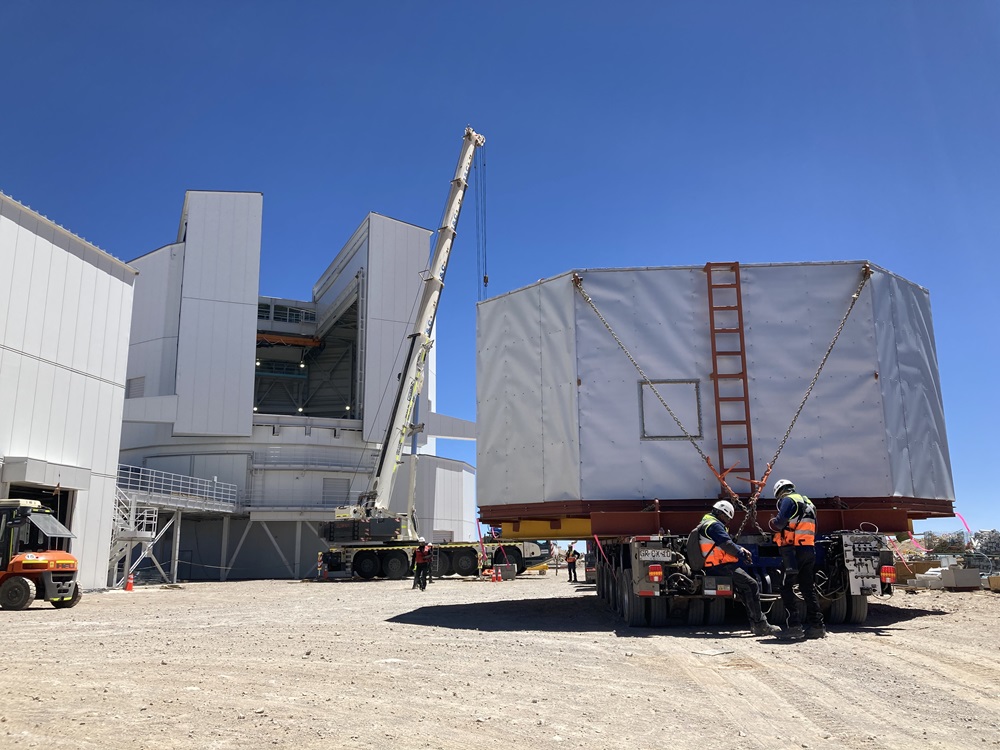
The chamber was transported in October 2024. The tandem trailer was used for transportation same as the trial run, taking our time and making sure it was safe. As a result, the transportation was completed successfully. It could be proceeded to install it in the operation building at the summit for evaluation test.
| |
▲Fig. 1. The chamber under transportation on the TAO road |
| |
▲Fig. 2. The chamber has successfully arrived at the summit! |
2. Installation in the operation building at the summit
The coating system was once assembled and carried out the test in Japan. That was implemented in a large factory where it was warm and mild environment for humans with 1 atmospheric pressure. However the assembly and installing are carried out in extremely harsh environment at an altitude of 5,640 meters. Therefore, confirming work procedures and preparing tools and equipment in advance, and health management of workers and process management are also important. Such preparations are required for all the tasks.
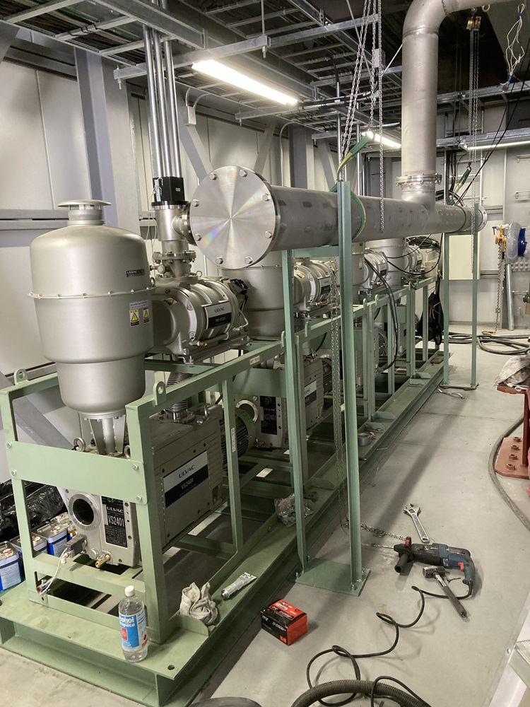
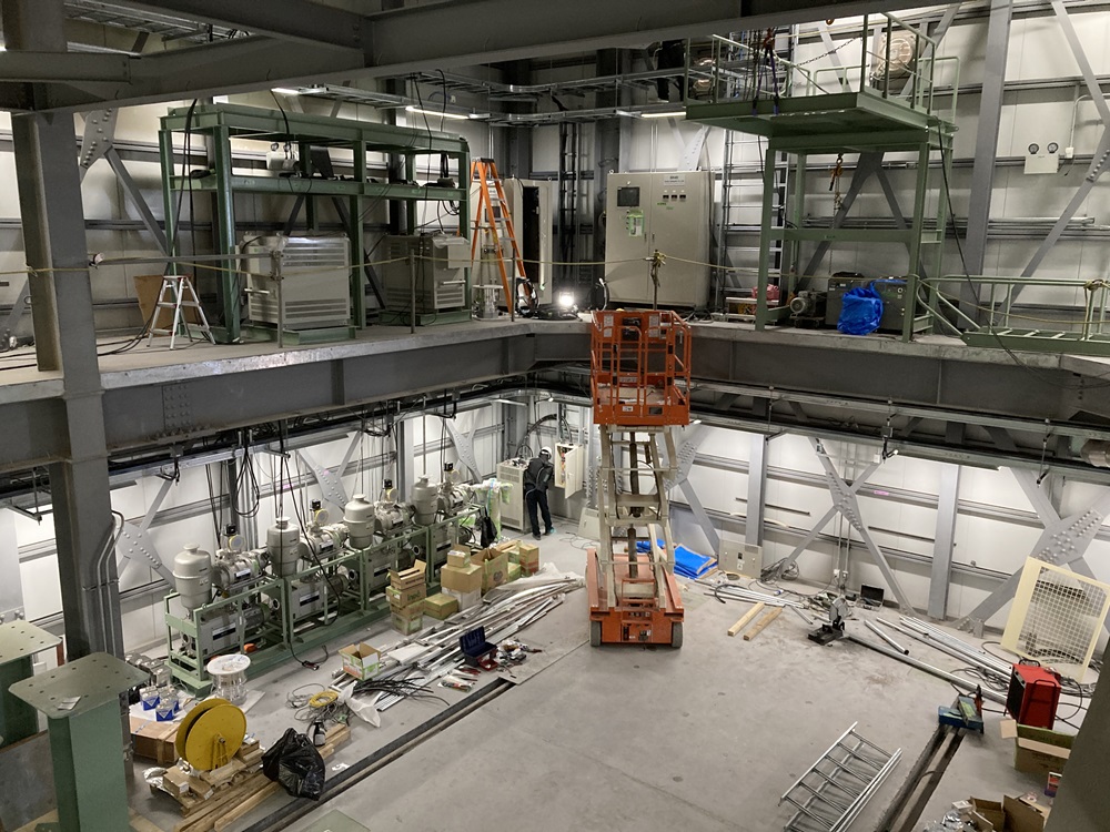
The coating system roughly includes the upper chamber, the lower chamber, the movable lifting cart, and the peripheral equipment. Each item is installed around coating chamber in the operation building before installation of the largest chamber. If there are mistakes in the procedure, it will not be completed. So all the installation work was proceeded carefully according to the installation plan. The peripheral equipment includes vacuum piping, cooling water piping, etc. which also need to be installed beforehand. For them,
additional on-site fabrication and adjustments were made to match the actual size in site.
|
| |
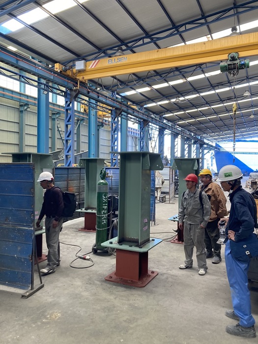
▲(left) Fig. 3. Rough pump and piping (right) Fig. 4. Peripheral equipment placed in the crammed space |
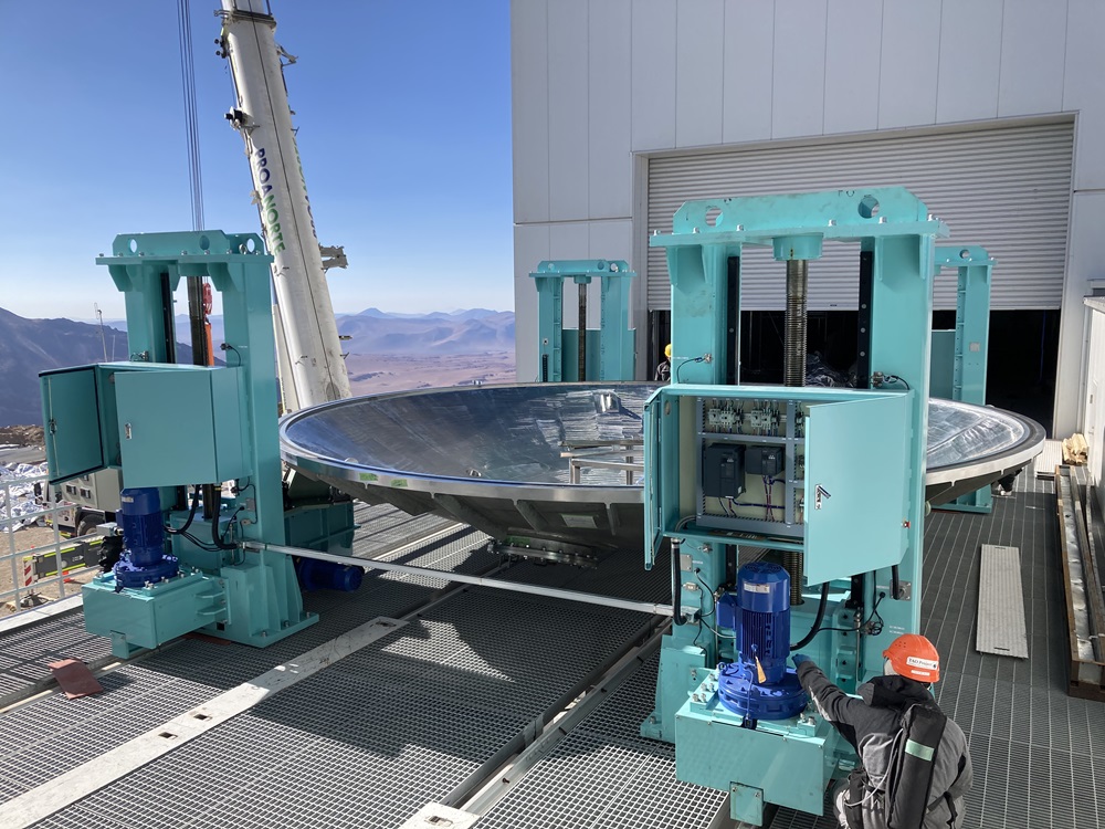
As mentioned before, one of the features of coating system for TAO is the lower chamber and the movable lifting cart are integrated. They were assembled on the bridge between the operation building and the enclosure. The movable lifting cart establishes its shape and functions after combination with the lower chamber. Each leg of the cart and the lower chamber were lifted carefully by the large crane and assembled.
|
| |
▲(left) Fig. 5. The lower chamber was lifted to the bridge. (right) Fig. 6.: The movable lifting cart (the jack) and the lower chamber were assembled. |
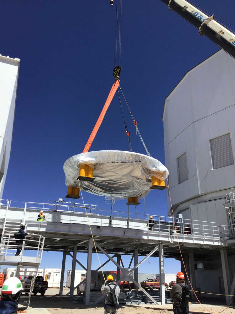
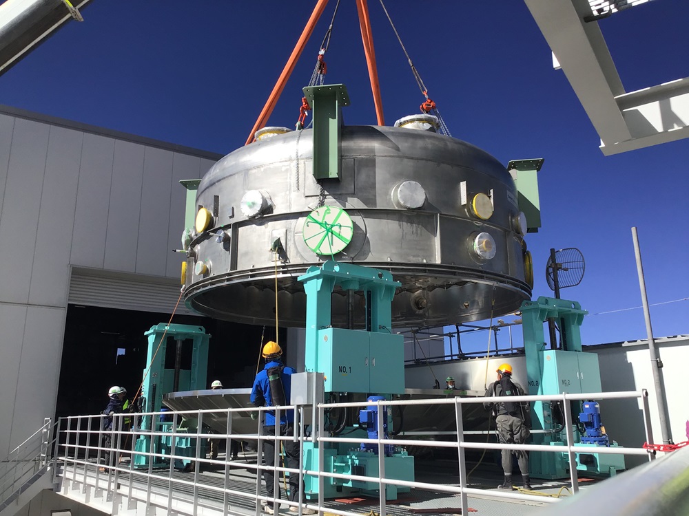
Next step was to install the upper chamber which is the largest and heaviest component among the TAO facilities. This step required very high crane operation techniques. It was necessary not only communication between the crane operator and the rigger (the indicator) but also understandings and coordinate the work process in advance. After the detailed and repetitive meetings, the upper chamber was set on the lower chamber. Then the upper chamber will be transported into the operation building, jacked up, and set to the ceiling of the operation building. Four intermediate supports between the ceiling support and the upper chamber were adopted in order to install the chamber horizontally and securely. For welding and other additional fabrication of these parts, we used the facilities and space of a company in Calama. (In addition, the cooling water piping was cut and threaded by a contractor in Calama. The installation of the upper chamber was possible with the cooperation of many local vendors.)
The installation of upper chamber which is the main event of this process, is achieved to set the chamber to the ceiling using the jack-up cart (with four legs which can be independently) and to fix with 32 bolts. The moment the installation was finally completed, we shared our joy together with many people involved in the development and manufacturing, and the workers. This upper chamber will not be removed during the operation as well as the telescope, and will be enshrined at the back of the operation building.
|
| |
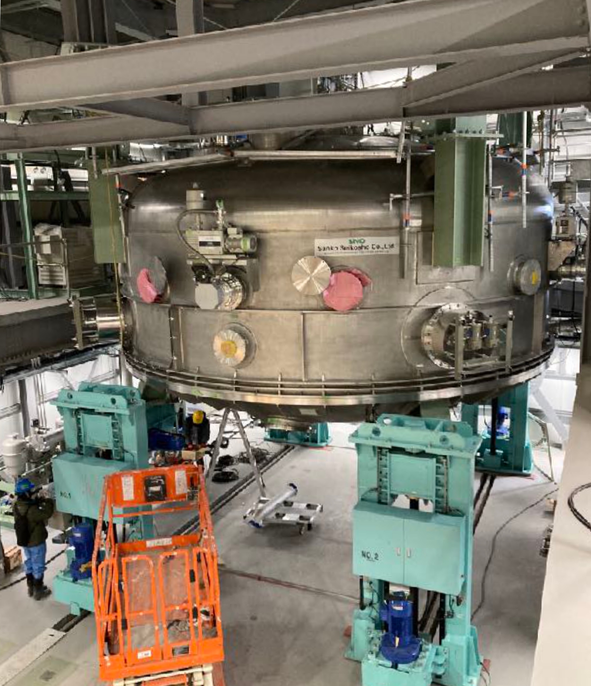
▲(left) Fig. 7. Lifting the upper chamber (right) Fig. 8. Assembled movable-lifting cart, the lower chamber, the upper chamber |
| |
▲Fig. 9. Processing the intermediate supports at the factory in Calama |
| |
▲Fig. 10. The coating chamber mounted at the ceiling in the operation building |
As issues of consideration, distortion between the flanges of the upper and lower chambers after combination of two chambers was found. It was found that when the lower chamber is set on the lifting jack, the lifting jack collapses outward, causing the lower chamber flange to deform convexly to the upper side. It has been confirmed that this distortion is eliminated when the two chambers are mated in the coating area and it is possible to achieve vacuum. But refurbishment is necessary to ensure safety and reliability of sandwiching and transporting the primary mirror cell and performing coating works. Improvement of the structure is currently under consideration.
3. Operation Test
Although there is no primary mirror cell this time, the evaluation test was carried out with the upper and lower chambers combined. After the chamber ancillary equipment, such as vacuum pump and cryopump, were installed, start-up test was carried out and adjustment/confirmation of operating parameters were checked. The confirmation of cooling water circulation of refrigerator compressor, helium gas pressure, and startup and operation test of the vacuum pump were also executed. In parallel with that work, the 144 filament wires were set and checked electrically.
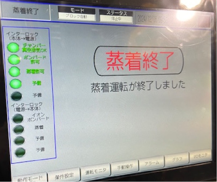
After checking the electrical equipment, a start-up test of the ion bombardment and the coating filament were conducted. The results of these tests were favorable, confirming that all equipment was functional. Although there are some sensor defects and adjustments of operating parameters are needed, this will be optimized through repeated coating tests before the actual coating works.
After assembling the telescope, we will finally proceed to transportation of the primary mirror to the summit and the first primary mirror coating. We are looking forward to the time when the primary mirror is given a life.
| |
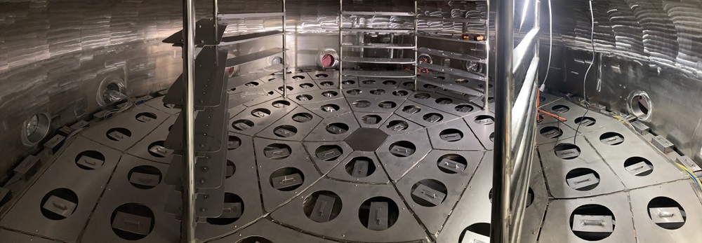
▲Fig.11. Inside view of the upper chamber. There are filament boxes on the floor. |
| |
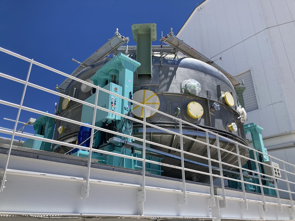
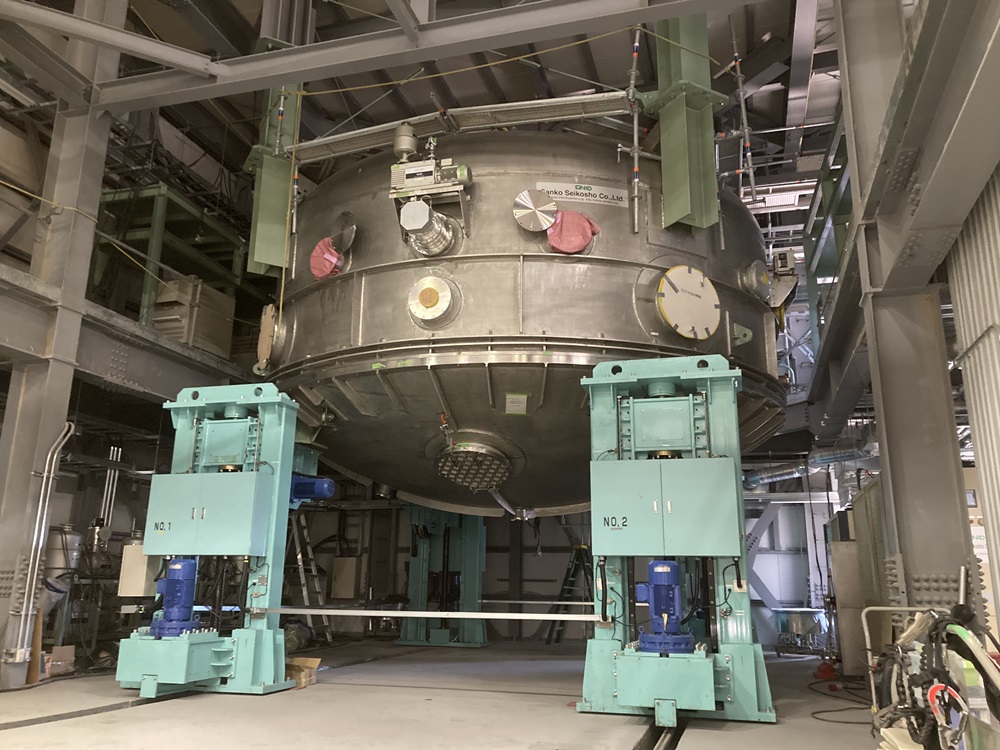
▲Fig.12. Overall view of the chamber with attached equipment |
|
| |
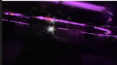
▲(left) Fig.13. Ion bombard energizing (right) Fig.14. Coating test finished! |
|